My nice shiny new ASR33 controller boards arrived today, and I am really pleased to say it worked first time, and is now running my teletype.
My previous approach was to use a more generic ESP32 board. Indeed, I used a simple dev board for my first attempt, and then a smaller generic board I had made. This did work, mostly.
To send to the Teletype 20mA I was able to simply use a resistor to limit current to 20mA from a 3.3V GPIO line. The ASR33 has a transistor input, so that actually worked well.
The receive side should be simple - the teletype just makes or breaks a circuit. So a simple pull up resistor and then the teletype loop grounding a GPIO pin. Well, should work, in theory.
Sadly it was never good. It depended massively on the distributor with carbon brushes, and leaf contacts, and was, shall we say, flaky. Yes, if you exercised the distributor (hold REPEAT and RETURN) for a while, it would clean up enough to work most of the time, but still not 100% reliable. Looking on a scope it was clear why it was so bad - the signal was just horrid.
The solution is a completely new dedicated ASR33 controller board.
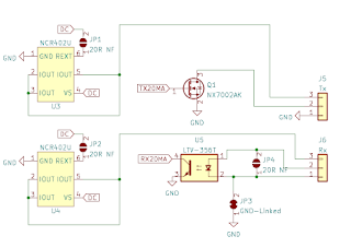
The first thing I did was to find a suitable 20mA source. I picked the NCR402U constant current source designed for LEDs. It defaults to 20mA but has an option of a resistor to change this. This also has the advantage that it can run off a higher voltage if needed, though the ASR33 does not need that. I needed two of these, one for Tx and one for Rx as the ASR33 is passive on SEND and RECEIVE sides.For sending, I then used a simple FET to connect the signal to ground. This means I have a 20mA source out, and a return which connects via a FET to ground, and causes 20mA to flow. The result is very clean, and drives the teletype nicely. But, as I say, just using a simple resistor off a GPIO also worked.
For receiving, I originally tried the 20mA via the teletype SEND circuit, and to a resistor. This should give me a simple voltage on a GPIO pin which relates to the current, 20mA or open circuit. It should be simple. But no, just as noisy as the original solution. The fix was to fit an optocoupler. The 20mA source goes via the teletype SEND circuit and then through an LED in the optocoupler. The output then goes in to a GPIO with an internal pull up. This is clean. Very clean indeed.
The result is both Tx and Rx working perfectly. I am very pleased with the result, and it makes the whole teletype much more usable.
Passive or active?
The ASR33 is passive for SEND and RECEIVE, but some teletypes could be active, so for that reason the Tx site FET can be used without the current source, and similarly the Rx optocoupler can be connected without using the current source.
I also added pads to allow a change to 60mA. However I don't have a 60mA teletype, and they typically drove a selector solenoid directly. That will not work from the 5V USB, and the board can only really do 40V which is unlikely to work even if at 60mA. Something to try when I send a board to someone with such a teletype.
More than just Tx and Rx?
The only standard connection on the teletype 20mA loop connections for Tx and Rx, but you usually want a little more. In this case a power control. I used a simple solid state relay to control the power to the whole machine, driven from a GPIO pin. But I also coded use of MQTT to work an external power switch running tasmota if needed. This allows the teletype to turn on, do something, and turn off, nicely.
Sadly having motor start at the same time is a problem as you get duff characters clocked in. The answer to this was fit an extra lead in to the teletype to allow the motor's power to be switched, using another solid state relay. This means the motor can start and stop while the power is still on, and ensure a clean start and stop without a duff random character (it actually clocks a non printing RO character).
But there is more ... if the ESP32 is controlling power, you need a power switch. For this I have one more GPIO to go to a button. My teletype has a MOTOR START button from an original, and more complex, motor control circuit. This was bypassed and run to the controller to allow it to be used to power on and off.
Of course I also have a multi-colour LED and a button to force a config more (WiFi AP and simple setting page to set WiFI and MQTT details).
Why?
The basic purpose is to allow a teletype to connect via a simple TCP socket. This makes it a lot easier to work with any modern computer system than an actual serial lead.
But it also does a few other things, a local echo, an punching large text on paper tape, and even a game of colossal cave built in. I mean why not?


No comments:
Post a Comment
Comments are moderated purely to filter out obvious spam, but it means they may not show immediately.