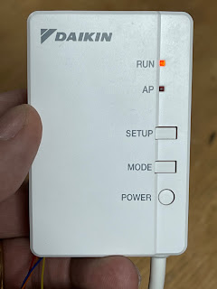
One aspect of the system is the Daikin WiFi module. It is a plug in thing for the ducted units, and built in (but still a unit on a wire in a slot) for the wall mount unit.
It used to be that Daikin WiFi modules worked locally, on the (WiFi) LAN, with an app, and have a rather easy to use http based API with which loads of software is already designed to work. There is a big open source community one this.
Sadly the latest version is different. It is "cloud based", not local control. Seriously, why do this? I mean, as an "option", OK, but killing local control is not good. This really is not good Daikin. I do not need "cloud control" (aka "dependancy") for things in my home.
Also, weirdly, it broadcasts its SSID even when on my WiFi, which is also stupid. I won't want it advertising or being vulnerable. So no!
As a result, today, I decided to tackle this issue.
Reverse engineering!
I decide to look at the connections it has to the main unit. They look simple. Checking with a meter I see DC around 17V, and a couple of wires. There was also a 5V line, but not connected. So looks pretty simple, GND, DC, and two signal wires at around 5V. I could have laid bets on the signals being 9k6 serial data, and they are. What a surprise.
So, oscilloscope, and we see, they are indeed 9k6, even parity, 1 stop bit, serial data, half duplex (poll and response) packet protocol.
So, what next, well.. Some debug...
With the serial data now connected to an ESP32, and some logging, I was quickly all to dump packets of data sent. The format did not look complex, some headers, length, a simple checksum, and so on.Of course, using the "cloud" system I could generate commands, and dump them. I quickly worked out how I set the temperature, the fan speed, the mode, and so on.
I have a load of status responses too, that need a bit of work - various temperatures. But not too hard.
So next step is trying to emulate the controller myself. One issue is the signals are all 5V and my stuff is all 3.3V.
However, the ESP32 can generally cope with 5V coming in, and 3.3V seems good enough for the air-con to see the 1's and 0's. So good enough for a proof of concept. A proper board will need some protection from the 5V, which is not hard.
The new controller
The new controller was made from a simple generic board to start with. I now have designs for a "proper" board, but this was good to prove it works.
The board is small! A fraction of the size of the Daikin module. But it works! I can power on/off, set the temperature, the mode, the fan speed, and so on.
So now to tidy the code, document it, do more tests with a wall mount unit with a lot more settings, make the PCB design and order some samples, and so on. Much to do.
I also want a nice web interface, nice MQTT interface, and maybe even make it backwards compatible with the older Daikin WiFi modules to allow a variety of apps to work. Oh, and stop sending its SSID when on-line locally!
But making a new Daikin WiFi aircon control module is not bad for a Saturday, and still time for hot tub, and curry.
It is all open source, and on GitHub, even if a bit of a work in progress. But yes, I think this will be a useful product.
P.S. I then found the wall mounted unit is a different model that talks a completely different serial protocol at a different speed, so spent Sunday making that work as well.


Rather than just adding 5v protection you might as well implement a logic level converter as it’s almost as simple.
ReplyDeletehttps://learn.sparkfun.com/tutorials/bi-directional-logic-level-converter-hookup-guide/all
That needs a 5V supply though? The protection will be a FET on input.
DeleteThat needs a 5V supply though? The protection will be a FET on input.
DeleteYou want a CD74HC4050E IC BUFFER. That will convert 5v logic to 3.3v :-)
Delete5V down to 3.3V is now issue, and a single FET is an easy way to do it. That chip would be crazy for one signal like this. The other way 3.3V to 5V needs a 5V supply.
DeleteLove to test this and capture packets replacing the BRP069B41 on units that support radiant heat (Nexura FVXG-K)
ReplyDelete